Coaxial Probe Fixturing
Coaxial Probe Fixturing
Coaxial Probe Fixturing
For high frequency testing, IDI’s patented Coaxial Spring Probe provides electrical performance up to 3 GigaHertz (with shielding plunger) and 500 MegaHertz (without shielding plunger).
Coaxial Probes have the option of being double-ended (compliant on both ends) or single-ended (compliant on one end), and most have an option for a flanged contact barrel. Many single-ended coaxial probes come with a pre-attached coaxial cable and are terminated with an optional SMA or SMB connector (other connector options are also available. Other coaxial probe designs include: coaxial probe with a built-in SMB connector and non-rotating shielding plunger. Most coaxial probe assemblies have signal conductors that are often replaceable with a standard probe (consult factory for probe replacement options). Other options include smooth-faced or serrated shielding plungers.
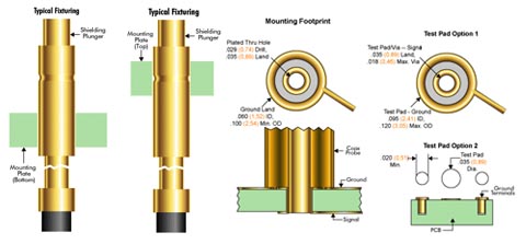
Coaxial probes with a flanged barrel can be mounted via two fixture plates. The two fixture plates are mounted above and below the flange and bolted together at the fixture corners for retention as seen in the figure above. Caution should be used in this fixturing arrangement when using a pre-attached SMA connector or other large connector on the end of the coaxial cable. The diameter of the SMA connector is larger in diameter than the contact barrel of the coaxial probe. This makes it impossible for the coaxial probe with connector to slip through the bottom fixture plate.
An alternative to the two-plate method is a press fit mount into one plate, whether the coax probe is flanged or unflanged. Again, with single ended probes, a cable may be threaded through a plate or plated through hole. For double ended probes, proper orientation needs to be confirmed before mounting the probes in place. Tooling may be needed to aid in the mounting process. For all probes, care must be taken to hold a tight tolerance on the mounting hole to ensure the amount of holding force needed. Once again, the size of connector may need consideration before using this method of fixturing. Proper positioning of unflanged coaxial probes and hole tolerancing are left to the discretion of the customer.
A different method for fixturing coaxial probes is to simply epoxy the contact barrel to the fixture substrate. This method can be used for virtually all IDI coaxial probes. This method may make the probes more complicated for replacement. But it is uncommon for whole coaxial probe assemblies to be replaced because the signal conductor of the assembly is often replaceable.
Similar to the epoxy method, solder can also be used for fixturing coaxial probes. Using a temperature-controlled application, solder instead of epoxy can be used to hold the contact barrel to the fixture substrate. This method can also be used for virtually all IDI coaxial probes and may offer better electrical conductivity than epoxy. Coaxial probes such as the 100304 and 100305 series can be surface mounted using the signal pin tail for positioning in a mounting hole. However, like the epoxy method, entire probe assemblies may be more difficult to replace. Care is needed in the soldering technique to avoid damage due to prolonged and excessive heating. Other standard soldering techniques should also apply.
These methods are offered based on previously observed applications. These or other methods of fixturing coaxial probes should be chosen by the customer based on specific applications and experiences. The footprint of test pad/via, signal test pad and ground test pad should be laid out similar to the footprint illustrated in the figure below. The test pad for the ground is only required for coaxial probe applications using the shielding plungers. Consult factory for alternate tip styles and other probe options.