Technical Definitions
Technical Definitions
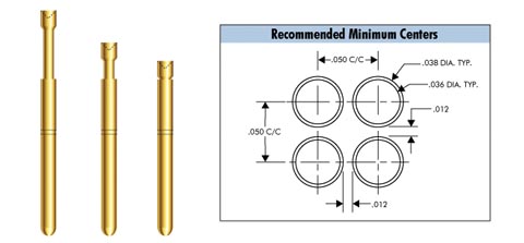
Recommended Minimum Centers
To prevent a potential shorting of probes, a clearance between probes is required. The recommended minimum centers, the minimum distance between the center-point of one mounting hole to the next, is determined by the probe geometry. The physical area occupied by the probe is determined by the plunger tip diameter plus it’s pointing accuracy, or the mounting hole diameter, whichever is larger.
The hole diameter and the center distance between probes dictate the amount of mounting plate material between receptacles. The amount of material is critical in maintaining the stiffness of the mounting plate. Should the integrity of the mounting plate be endangered, possible alternatives include choice of different material, a thicker mounting plate or use of smaller diameter probes.
Current Rating
The current of the Spring Contact Probe is determined by the power (heat) generated by the current and resistance (I2R) and the ability of the probe and mounting plate to dissipate this heat. The base material, plating and bulk size of the probe are critical in determining the current rating. Also taken into consideration are the mounting centers, the mounting material, the ambient temperature and the duty cycle.
Contact Resistance
The resistance of a Spring Contact Probe is dependent upon the base materials, platings and physical design. The typical current path of a probe is from the plunger to the barrel and then through the receptacle and out to the wire. Approximately 99% of the current will follow this path. The remaining 1% of the current will flow through the spring.
Spring Force
Spring force is the amount of force required to compress a probe’s plunger to a specified distance. IDI offers a wide range of spring forces. Lower force springs are typically used in vacuum fixtures with a high probe population and applications in which witness marks are undesirable. Higher force springs are available for penetrating contaminated test points in lower density areas. IDI uses a helical compression spring. The spring rate of a helical coil spring is determined primarily by the following design factors: spring material, wire diameter, spring diameter and number of coils per unit length. While spring design is a complex process, determining the spring force at various deflections not specified in the IDI Catalog is simple. Since spring forces are linear (F=kx), the following formulas give the spring force at any given deflection.
Recommended Working Travel
The recommended working travel, also known as rated travel, is typically 2/3 of the maximum travel. Depending on the spring design, compressing a probe beyond its recommended working travel can create undue stress on the spring. The fully compressed length of probes can vary up to .010″ (0.25) without considering variations in receptacle mounting heights. Consequently, testing at full stroke can potentially damage the plunger tip or the device under test (DUT). If testing past recommended working travel is required, please contact IDI for assistance in choosing a probe for your specific requirements.
Maximum Travel
Maximum travel is the maximum distance that a probe may be compressed. The small body diameter of the probe controls the maximum travel if the probe tip is headless. If the probe tip is headed, the bottom of the tip making contact with the barrel controls the maximum travel distance. The maximum travel listed in the IDI Catalog is based upon a nominally dimensioned part. It should be noted that the maximum travel has a tolerance of + .005″ (0.13).
Operating Temperature
Lubrication and spring materials determine the operating temperature of a probe. Most all probes that are lubricated to increase mechanical life, have a maximum operating temperature of 120°C Probes operating outside of this range should be non-lubricated. Spring material is the other factor affecting the maximum operating temperature of a probe. Various materials lose their spring properties (anneal) at different temperatures. The chart below lists the operating temperatures for the various spring materials lubricated and non-lubricated.
Pointing Accuracy
Probe pointing accuracy is the maximum radial departure of a probe tip from the center line of the probe barrel. There are several variables that contribute to the pointing accuracy of a probe. Those variables include tolerances related to the probe. Additional variables are encountered during fixturing and they include: probe and receptacle tolerance and the test fixture. The formulas below calculate pointing accuracy for the IDI Catalog probes.
Standard Design:
- S-0 Probe
- SX-0 Probe
- ICT-100 Probe
- S-100 Probe
Tolerance extremes, as well as several other variables, are not addressed by this formula. To determine the minimum required pointing accuracy in any given application, use the following formula:
Life Expectancy
Generally, IDI probes are rated at 1,000,000 cycles minimum in laboratory testing. Actual life in the field is dependent upon several factors including proper use, fixture quality, temperature/cleanliness of environment and maintenance.